|
|
|
|
|
|
|
|
|
|
|
|
|
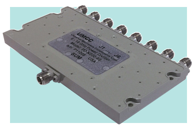
| 8-Way Dividers | |
|
|
|
|
- Specifications are
subject to change without notice - Click on the product model number for Specifications-Sheet in PDF - Click on " |
|
|
Sales/Technical Contact Email: Sales@UMCC111.com |
|
Low Frequency
Wide Band 8-Way Dividers |
||||||||||
| Model Number |
Freq. Range (MHz) |
Insertion
Loss (1) (dB) Max |
Isolation (dB) Min |
VSWR ; Max | Amplitude Balance (dB) Max |
Phase Balance (deg) Max |
Power
(2) cw/avg Load VSWR |
Outline Drawing |
||
| SUM | OUTS | >> 2:1 | << 2:1 | |||||||
| 10 KHz - 30 MHz | ||||||||||
|
PS-0030-8S with SMA(f) PS-0030-8B with BNC(f) PS-0030-8N with N(f) |
0.01 - 0.02 | 0.8 | 28 | 1.50 | 1.50 | -/+ 0.2 | -/+ 1 deg | 4 W | 10 W | Fig.21 |
| 0.02 - 10 | 1.30 | 1.30 | ||||||||
| 10 - 30 | 1.2 | 20 | ||||||||
|
500 KHz - 100 MHz (High Isolation) |
||||||||||
|
PD-0100-8S with SMA(f) PD-0100-8B with BNC(f) PD-0100-8N with N(f) |
0.5 - 100 | 1.2 | 30 | 1.20 (1.5:1 over 0.5-3 MHz) |
1.20 (1.4:1 over 0.5-3 MHz) |
-/+ 0.1 | -/+ 1 deg | 2 W | 8 W | Fig.22 |
| 500 KHz - 250 MHz | ||||||||||
|
PD-0250-8S with SMA(f) PD-0250-8B with BNC(f) PD-0250-8N with N(f) |
0.5 - 250 | 1.7 | 25 | 1.25 (1.5:1 over 0.5-3 MHz) |
1.25 (1.4:1 over 0.5-3 MHz) |
-/+ 0.2 | -/+ 2 deg | 2 W | 8 W | Fig.22 |
| 1 - 500 MHz | ||||||||||
|
PS-0500-8S with SMA(f) PS-0500-8B with BNC(f) PS-0500-8N with N(f) |
1 - 500 | 2.0 | 20 | 1.30 (1.4:1 over 1-2 MHz) |
-/+ 0.5 | -/+ 3 deg | 2 W | 8 W | Fig.21 | |
| 10 - 1000 MHz | ||||||||||
|
PS-1000-8S with SMA(f) PS-1000-8B with BNC(f) PS-1000-8N with N(f) |
10 - 500 | 1.3 | 23 | 1.35 | 1.35 (1.45:1 over 10-20 MHz) |
-/+ 0.2 | -/+ 1 deg | 4 W | 10 W | Fig.21 |
| 500 - 1000 | 1.8 | -/+ 0.3 | -/+ 2 deg | |||||||
| 20 - 3000 MHz | ||||||||||
|
PS-3000-8S with SMA(f) PS-3000-8N with N(f) |
20 - 50 | 2.0 | 18 | 1.50 | 1.70 | -/+ 0.1 | -/+ 1 deg | 2 W | 8 W | Fig.23 |
| 50 - 1000 | 1.50 | -/+ 0.2 | -/+ 3 deg | |||||||
| 1000 - 2000 | 3.0 | -/+ 0.5 | -/+ 5 deg | |||||||
| 2000 - 3000 | 4.4 | |||||||||
1) Loss due to division is 9.03dB 2) Power at SUM port |
||||||||||
|
Narrow-Band 8-Way Dividers |
||||||||||
| Model Number |
Freq. Range (GHz) |
Insertion
Loss (1) (dB) Max |
Isolation (dB) Min |
VSWR Max |
Amplitude Balance (dB) Max |
Phase Balance (deg) Max |
Power
(2) cw/avg Load VSWR |
Outline Drawing |
||
| SUM | OUTS | >> 2:1 | << 2:1 | |||||||
|
PS-C000-8S |
1 - 2 | 0.8 | 20 | 1.40 | 1.20 | -/+ 0.2 | -/+ 2 deg | 2 W | 20 W | Fig.1 |
| PS-D000-8S | 2 - 4 | 0.8 | 20 | 1.50 | 1.35 | -/+ 0.3 | -/+ 2 deg | 1 W | 10 W | Fig.2 |
|
PS-3800-8S |
2.8 - 5.2 | 0.7 | 22 | 1.30 | 1.25 | -/+ 0.2 | -/+ 3 deg | 1 W | 10 W | Fig.5 |
|
PS-E000-8S |
4 - 8 | 0.8 | 22 | 1.40 | 1.30 | -/+ 0.2 | -/+ 3 deg | 1 W | 10 W | Fig.6 |
|
PD-G000-8S |
8 - 17 | 1.5 | 17 | 1.6 | 1.50 | -/+ 0.3 | -/+ 5 deg | 1 W | 10 W | Fig.8 |
| PD-P000-8S | 10 - 20 | 2.2 | 16 | 1.70 | 1.60 | -/+ 0.5 | -/+ 6 deg | 1 W | 10 W | Fig.8 |
|
1) Loss due to division is 9.03dB 2) Power at SUM port |
||||||||||
|
Wide-Band 8-Way Dividers 1.9 - 18 GHz |
||||||||||
| Model Number |
Freq. Range (GHz) |
Insertion
Loss (1) (dB) Max |
Isolation (dB) Min |
VSWR Max |
Amplitude Balance (dB) Max |
Phase Balance (deg) Max |
Power
(2)
cw/avg Load VSWR |
Outline Drawing |
||
| SUM | OUTS | >> 2:1 | << 2:1 | |||||||
|
PD-L000-8S |
1.9 - 8.5 | 1.6 | 18 | 1.70 | 1.40 | -/+ 0.3 | -/+ 3 deg | 1 W | 10 W | Fig.4 |
|
PD-MS00-8S Slimline Pkg. |
3.6 - 13.4 | 1.5 | 18 | 1.50 | 1.40 | -/+ 0.2 | -/+ 4 deg | 1 W | 10 W | Fig.7 |
|
PD-NS00-8S Slimline Pkg. |
6 - 18 | 2.2 | 18 | 1.55 | 1.35 | -/+ 0.3 | -/+ 7 deg | 1 W | 10 W | Fig.10 |
|
1) Loss due to division is 9.03dB 2) Power at SUM port |
||||||||||
|
Multi-Octave-Band 8-Way
Dividers 2 - 18 GHz |
||||||||||
| Model Number |
Freq. Range (GHz) |
Insertion
Loss (1) (dB) Max |
Isolation (dB) Min |
VSWR Max |
Amplitude Balance (dB) Max |
Phase Balance (deg) Max |
Power
(2)
cw/avg Load VSWR |
Outline Drawing |
||
| SUM | OUTS | >> 2:1 | << 2:1 | |||||||
|
PD-SS00-8S Slimline Pkg. |
2 - 18 | 3.3 | 16 | 1.80 | 1.50 | -/+ 1.0 | -/+ 10 deg | 1 W | 10 W | Fig.7 |
|
1) Loss due to division is 9.03dB 2) Power at SUM port |
||||||||||
| All Models: | |
| 50 Ω Nominal | |
| SMA(f) , ("unless otherwise specifies") | |
Environmental Ratings: |
||
| - Operating | -55 degC to +95 degC | |
| - Storage | -60 degC to +110 degC | |
| Mil-STD-202F, Method 103B Condition B | ||
| Mil-STD-202F, Method 213B Condition B | ||
| Mil-STD-202F, Method 204D Condition B | ||
| Mil-STD-202F, Method 105C Condition B | ||
| Mil-STD-202F, Method 107D Condition B | ||
|
|
|
|
|