|
|
|
|
|
|
|
|
|
|
|
|
|
| SP4T Switches / Phase Matched | |
|
|
|
|
Sales/Technical Contact Email: Sales@UMCC111.com |
|
RF Circuit / Reflective SP4T |
RF Circuit / Absorptive SP4T |
|
|
|
|
|
|
|
Common Specifications | |
|
|
Available Options | |
|
> Specifications are subject to change
without notice > for Specifications-Sheet in PDF, click on the product model number > to see the actual response curves, click on " |
Broadband SP4T Switches (Reflective
/ Absorptive)
Frequencies from 20MHz to 15GHz
|
Model
No. |
Frequency (GHz) |
Insertion
Loss (dB) Max |
Isolation (dB) Min |
VSWR Max |
Rise/Fall
Time Max |
On/Off Time Max |
Power Handling, Max |
Supply Voltage |
Outline Drawing |
|
| Cw / Avg | Peak | |||||||||
| 20 MHz - 6 GHz | ||||||||||
|
SW-B300-4S (Reflective) |
0.02 - 6 | 2.7 | 70 |
1.5:1 (1.7:1 Over 20-30MHz) |
200 ns | 300 ns |
+27dbm (+23dBm Max Below 100MHz) |
5W (5μS, PW) |
+5(-/+0.25)V / 60mA -12(-/+0.5)V / 80mA |
Fig.1 |
|
SW-B310-4S (Absorptive) |
0.02 - 6 | 2.7 | 75 |
1.5:1 (1.7:1 Over 20-30MHz) |
200 ns | 300 ns |
+27dbm (+23dBm Max Below 100MHz) |
5W (5μS, PW) |
+5(-/+0.25)V / 130mA -12(-/+0.5)V / 80mA |
|
| 0.2 - 4 GHz | ||||||||||
|
SW-DA3W-4S (Reflective) |
0.2 - 4 | 1.8 | 70 | 1.5:1 | 350 ns | 400 ns | +27dbm |
5W (1μS, PW) |
+5(-/+0.25)V / 70mA -12(-/+0.5)V / 70mA |
Fig.1 |
|
SW-DA1W-4S (Absorptive) |
0.2 - 4 | 1.8 | 75 | 1.5:1 | 250 ns | 300 ns | +27dbm |
5W (1μS, PW) |
+5(-/+0.25)V / 140mA -12(-/+0.5)V / 70mA |
|
|
2 - 14 GHz (Fast Switching) |
||||||||||
|
SW-L440-4S (Reflective) |
2 - 12.4 | 2.4 | 55 | 1.6:1 | 10 ns | 40 ns | +27dbm |
5W (1μS, PW) |
+5(-/+0.25)V / 60mA -12(-/+0.5)V / 70mA |
Fig.1 |
| 12.4 - 14 | 50 | |||||||||
|
SW-L410-4S (Absorptive) |
2 - 12.4 | 2.4 | 60 | 1.6:1 | 10 ns | 40 ns | +27dbm |
5W (1μS, PW) |
+5(-/+0.25)V / 140mA -12(-/+0.5)V / 70mA |
|
| 12.4 - 14 | 55 | |||||||||
|
0.4
- 14 GHz (Fast Switching) |
||||||||||
|
SW-J440-4S (Reflective) |
0.4 - 12.4 | 2.6 | 55 | 1.7:1 | 25 ns | 60 ns | +27dbm |
5W (1μS, PW) |
+5(-/+0.25)V / 60mA -12(-/+0.5)V / 70mA |
Fig.1 |
| 12.4 - 14 | 50 | |||||||||
|
SW-J410-4S (Absorptive) |
0.4 - 12.4 | 2.6 | 60 | 1.7:1 | 25 ns | 60 ns | +27dbm |
5W (1μS, PW) |
+5(-/+0.25)V / 140mA -12(-/+0.5)V / 70mA |
|
| 12.4 - 14 | 55 | |||||||||
| 1 - 15 GHz | ||||||||||
|
SW-K03W-4S (Reflective) |
1 - 6 | 2.7 | 70 | 1.7:1 | 350 ns | 400 ns | +27dbm |
5W (1μS, PW) |
+5(-/+0.25)V / 60mA -12(-/+0.5)V / 60mA |
Fig.1 |
| 6 - 12.4 | 60 | |||||||||
| 12.4 - 15 | 55 | |||||||||
|
SW-K01W-4S (Absorptive) |
1 - 6 | 2.7 | 75 | 1.7:1 | 250 ns | 300 ns | +27dbm |
5W (1μS, PW) |
+5(-/+0.25)V / 120mA -12(-/+0.5)V / 60mA |
|
| 6 - 12.4 | 65 | |||||||||
| 12.4 - 15 | 60 | |||||||||
Broadband SP4T Switches (Reflective
/ Absorptive)
Frequencies from 100MHz to 20GHz
|
Model
No. |
Frequency (GHz) |
Insertion
Loss (dB) Max |
Isolation (dB) Min |
VSWR Max |
Rise/Fall
Time Max |
On/Off Time Max |
Power Handling, Max |
Supply Voltage |
Outline Drawing |
|
| Cw / Avg | Peak | |||||||||
| 2 - 18 GHz | ||||||||||
|
SW-S200-4S (Reflective) |
2 - 10 | 2.4 | 60 | 1.8:1 | 25 ns | 70 ns | +30dbm |
10W (1μS, PW) |
+5(-/+0.25)V / 140mA -12(-/+0.5)V / 70mA |
Fig.1 |
| 10 - 18 | 50 | |||||||||
|
SW-S270-4S (Absorptive) |
2 - 10 | 2.8 | 65 | 1.85:1 | 30 ns | 70 ns | +24dbm |
5W (1μS, PW) |
+5(-/+0.25)V / 140mA -12(-/+0.5)V / 70mA |
|
| 10 - 18 | 55 | |||||||||
|
SW-S01W-4S (Absorptive) |
2 - 6 | 3.0 | 90 | 1.8:1 | 150 ns | 250 ns | +27dbm |
5W (1μS, PW) |
+5(-/+0.25)V / 120mA -12(-/+0.5)V / 60mA |
|
| 6 - 12 | 80 | |||||||||
| 12 - 18 | 70 | |||||||||
|
SW-S510-4S (Absorptive) Fast Switching |
2 - 9 | 2.8 | 70 | 2:1 | 15 ns | 40 ns | +27dbm |
5W (1μS, PW) |
+5(-/+0.25)V / 120mA -12(-/+0.5)V / 60mA |
|
| 9 - 18 | 60 | |||||||||
|
SW-S000-4S (Reflective) |
2 - 18 | 2.6 | 70 | 1.8:1 | 25 ns | 70 ns | +30dbm |
10W (1μS, PW) |
+5(-/+0.25)V / 160mA -12(-/+0.5)V / 70mA |
|
|
SW-S070-4S (Absorptive) |
2 - 18 | 3.4 | 75 | 1.9:1 | 30 ns | 70 ns | +24dbm |
5W (1μS, PW) |
+5(-/+0.25)V / 160mA -12(-/+0.5)V / 70mA |
|
| 0.5 - 18 GHz | ||||||||||
|
SW-U200-4S (Reflective) |
0.5 - 10 | 2.6 | 60 | 1.8:1 | 25 ns | 70 ns | +30dbm |
10W (1μS, PW) |
+5(-/+0.25)V / 140mA -12(-/+0.5)V / 70mA |
Fig.1 |
| 10 - 18 | 50 | |||||||||
|
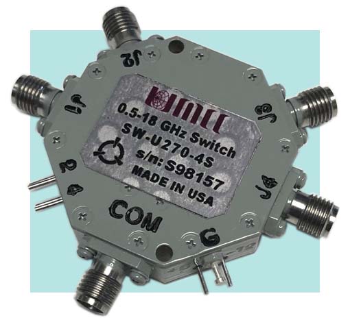
SW-U270-4S (Absorptive) |
0.5 - 10 | 3.0 | 65 | 1.9:1 | 30 ns | 70 ns | +24dbm |
5W (1μS, PW) |
+5(-/+0.25)V / 140mA -12(-/+0.5)V / 70mA |
|
| 10 - 18 | 55 | |||||||||
|
SW-U01W-4S (Absorptive) |
0.5 - 6 | 3.2 | 90 | 1.8:1 | 150 ns | 250 ns | +27dbm |
5W (1μS, PW) |
+5(-/+0.25)V / 120mA -12(-/+0.5)V / 60mA |
|
| 6 - 12 | 80 | |||||||||
| 12 - 18 | 70 | |||||||||
|
SW-U510-4S (Absorptive) Fast Switching |
0.5 - 9 | 3.2 | 70 | 2:1 | 20 ns | 50 ns | +27dbm |
5W (1μS, PW) |
+5(-/+0.25)V / 120mA -12(-/+0.5)V / 60mA |
|
| 9 - 18 | 60 | |||||||||
|
SW-U000-4S (Reflective) |
0.5 - 18 | 3.0 | 70 | 1.9:1 | 25 ns | 60 ns | +30dbm |
10W (1μS, PW) |
+5(-/+0.25)V / 160mA -12(-/+0.5)V / 70mA |
|
|
SW-U070-4S (Absorptive) |
0.5 - 18 | 3.4 | 75 | 2:1 | 30 ns | 80 ns | +24dbm |
5W (1μS, PW) |
+5(-/+0.25)V / 160mA -12(-/+0.5)V / 70mA |
|
| 0.1 - 18 GHz | ||||||||||
|
SW-V200-4S (Reflective) |
0.1 - 10 | 2.6 | 60 | 1.8:1 | 50 ns | 150 ns |
+30dbm (+27dBm Max Below 300MHz) |
5W (1μS, PW) |
+5(-/+0.25)V / 140mA -12(-/+0.5)V / 70mA |
Fig.1 |
| 10 - 18 | 50 | |||||||||
|
SW-V010-4S (Absorptive) |
0.1 - 6 | 3.0 | 90 | 1.8:1 | 150 ns | 250 ns | +27dbm |
5W (1μS, PW) |
+5(-/+0.25)V / 140mA -12(-/+0.5)V / 70mA |
|
| 6 - 12 | 80 | |||||||||
| 12 - 18 | 70 | |||||||||
|
SW-V000-4S (Reflective) |
0.1 - 18 | 3.1 | 70 | 1.9:1 | 50 ns | 150 ns |
+30dbm (+27dBm Max Below 300MHz) |
5W (1μS, PW) |
+5(-/+0.25)V / 160mA -12(-/+0.5)V / 70mA |
|
|
SW-V070-4S (Absorptive) |
0.1 - 18 | 3.6 | 75 | 2:1 | 50 ns | 150 ns | +24dbm |
5W (1μS, PW) |
+5(-/+0.25)V / 160mA -12(-/+0.5)V / 70mA |
|
| 2 - 20 GHz | ||||||||||
|
SW-P200-4S (Reflective) |
2 - 14 | 2.6 | 60 | 1.8:1 | 25 ns | 70 ns | +30dbm |
10W (1μS, PW) |
+5(-/+0.25)V / 140mA -12(-/+0.5)V / 70mA |
Fig.1 |
| 14 - 20 | 45 | |||||||||
|
SW-P01W-4S (Absorptive) |
2 - 6 | 3.2 | 90 | 1.8:1 | 150 ns | 250 ns | +27dbm |
5W (1μS, PW) |
+5(-/+0.25)V / 120mA -12(-/+0.5)V / 60mA |
|
| 6 - 12 | 80 | |||||||||
| 12 - 20 | 70 | |||||||||
|
SW-P510-4S (Absorptive) Fast Switching |
2 - 9 | 3.3 | 70 | 2:1 | 15 ns | 40 ns | +27dbm |
5W (1μS, PW) |
+5(-/+0.25)V / 120mA -12(-/+0.5)V / 60mA |
|
| 9 - 18 | 60 | |||||||||
| 18 - 20 | 55 | |||||||||
|
SW-P000-4S (Reflective) |
2 - 20 | 2.8 | 70 | 1.9:1 | 25 ns | 70 ns | +30dbm |
10W (1μS, PW) |
+5(-/+0.25)V / 160mA -12(-/+0.5)V / 70mA |
|
|
SW-P070-4S (Absorptive) |
2 - 20 | 3.7 | 75 | 1.9:1 | 30 ns | 70 ns | +24dbm |
5W (1μS, PW) |
+5(-/+0.25)V / 160mA -12(-/+0.5)V / 70mA |
|
| 0.3 - 20 GHz | ||||||||||
|
SW-G200-4S (Reflective) |
0.3 - 10 | 3.0 | 60 | 1.9:1 | 50 ns | 150 ns | +30dbm |
10W (1μS, PW) |
+5(-/+0.25)V / 140mA -12(-/+0.5)V / 70mA |
Fig.1 |
| 10 - 20 | 47 | |||||||||
|
SW-G01W-4S (Absorptive) |
0.3 - 12 | 3.3 | 80 | 1.8:1 | 150 ns | 250 ns | +27dbm |
5W (1μS, PW) |
+5(-/+0.25)V / 140mA -12(-/+0.5)V / 70mA |
|
| 12 - 20 | 70 | |||||||||
|
SW-G000-4S (Reflective) |
0.3 - 10 | 3.3 | 80 | 1.9:1 | 50 ns | 150 ns | +30dbm |
10W (1μS, PW) |
+5(-/+0.25)V / 160mA -12(-/+0.5)V / 70mA |
|
| 10 - 20 | 70 | |||||||||
|
SW-G070-4S (Absorptive) |
0.3 - 10 | 3.8 | 85 | 2:1 | 50 ns | 150 ns | +24dbm |
5W (1μS, PW) |
+5(-/+0.25)V / 160mA -12(-/+0.5)V / 70mA |
|
| 10 - 20 | 75 | |||||||||
| All Models: | ||
| 50 Ω Nominal | ||
| TTL, One Unit Load (1.6mA Sink / 40μA Source) | ||
| 4-Controls /
Floating-High Logic "0" for path "ON" ( 0 to +0.8V) Logic "1" for path "OFF" (+2.2 to +5.0V) |
||
| - RF Input / Output | SMA (female) | |
| - Supply | Solder Pins | |
| - Control | Solder Pins | |
Environmental Ratings: |
||
| - Operating | -55 degC to +95 degC | |
| - Storage | -60 degC to +110 degC | |
| Mil-STD-202F, Method 103B Condition B | ||
| Mil-STD-202F, Method 213B Condition B | ||
| Mil-STD-202F, Method 204D Condition B | ||
| Mil-STD-202F, Method 105C Condition B | ||
| Mil-STD-202F, Method 107D Condition B | ||
Available Options: 1) units with combination of the following options may require some specification tradeoffs from the standard 2) Some options may not be available on all models |
| A1)* +5 ( -/+ 0.25 )V / -5 ( -/+ 0.25 )V | G1) VF @ Common Port <> 0.25dB additional Loss | ||
| A2) +5 ( -/+ 0.25 )V / -15 ( -/+ 0.5 )V | G2) VF @ J1 - J4 Ports <> 0.25dB additional Loss | ||
| A3) +12 ( -/+ 0.5 )V / -12 ( -/+ 0.5 )V | G3) VF @ All Ports <> 0.5dB additional Loss | ||
| A4) +15 ( -/+ 0.5 ) V / -15 ( -/+ 0.5 )V | * Voltage spikes during switching transition can reach as high as few volts with bandwidths reaching up to near 1GHz. These Spikes/Video do appear on the switch RF port; this may effect certain systems that are sensitive to these undesirable voltage spikes. UMCC offers internal 3-section high-pass filtering (G options) to reduce these voltage spikes to a reasonable level of 50~400 mV Pk-Pk depending on the switch types. For more effective transient voltage reduction, an external higher order filtering is highly recommended. UMCC has developed series of miniature wideband filters for this very purpose. To see the available selection, please visit the following page: Filter-HighPass | ||
| *Additional Switching Delay (On/Off Time) | |||
| |
|||
| B1) J1 - J4 Ports with SMA(M) | |||
| B2) All SMA(M) | |||
| B3) COM Port with SMA(M) | |||
| F1) Inverted Logic, ("1" = Path "ON") | |||
| F2) Binary Coded Logic, (2 Controls + Enable) | |||
| > Outline
for Switch with Option "F2"
Fig.
3
|
|||
|
|
|
|
|