|
|
|
|
|
|
|
|
|
|
|
|
|
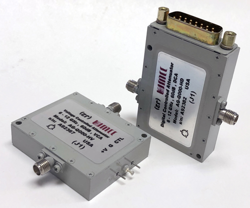
| Narrow Band High Range Variable Attenuators | |
|
|
|
|
Sales/Technical Contact Email: Sales@UMCC111.com |
| UMCC offers this selection of pin-diode variable attenuators in octave bands with high dynamic range to 80dB. Attenuators are equipped with a linearizer driver circuit for attenuation control setting. Control signal is via a voltage or a digital word. Attenuators are also available without a driver where control would be via a forward current. | |
|
RF Circuit |
Voltage Control Driver |
|
|
|
|
Digital Control Driver |
|
 |
|
|
|
Common Specifications | |
|
|
Available Options | |
|
> Specifications are subject to change
without notice |
|
|
| Voltage Controlled Attenuator (VCA) / "AT-X8XX-HV" Models |
| Digital Controlled Attenuator (DCA) / "AT-X8XX-HD" Models |
Specifications for Standard Models (80 dB Dynamic Range Maximum)
|
Model
No. |
Frequency (Ghz) |
Insertion
Loss (dB) Max |
VSWR Max |
Power
Rating Operating (CW/PK) Survival (CW/AVG) |
Settling Time (1) |
Attenuation Flatness (-/+ dB) |
Outline Drawing |
||||
| 10dB | 20dB | 40dB | 60dB | 80 dB | |||||||
| AG-H800-HV |
3
- 6 |
2.0 | 1.45:1 | +20dbm
(O) +30dbm (S) |
1μs (5μs<PW<0.1s) |
0.25 | 0.7 | 1.4 | 1.9 | 2.3 | -HV |
| AG-H800-HD | -HD | ||||||||||
| AG-N800-HV |
8
- 18 |
3.9 | 2:1 | +20dbm
(O) +30dbm (S) |
1μs (5μs<PW<0.1s) |
0.5 | 1.2 | 2.2 | 2.5 | 2.5 | -HV |
| AG-N800-HD | -HD | ||||||||||
|
1) "settling time" is defined as the time attenuation level transits from one attenuation level to within -/+1dB of another attenuation level |
|||||||||||
| All Standard Models: | |||
| 50 Ω Nominal | |||
| 80 dB Nominal | |||
| - Voltage Controlled Units (AT-X8XX-HV series) |
0V to +8V, Slope = 10dB/Volt, Impedance= 2.5K Ohms (0V = 0dB Attenuation (Reference)) |
||
|
- Digital Controlled Units
(AT-X8XX-HD series) |
9
Bit Positive Binary TTL ( LSB=0.25dB, MSB=64dB), Impedance= 5~10K Ohms |
||
| 0 - 0.8 dB | -/+ 50% Max | ||
| > 0.8 - 10 dB | -/+ 0.40 dB Max | ||
| > 10 - 30 dB | -/+ 0.50 dB Max | ||
| > 30 - 50 dB | -/+ 0.90 dB Max | ||
| > 50 - 70 dB | -/+ 1.35 dB Max | ||
| > 70 - 80 dB | -/+ 1.85 dB Max | ||
| +12 to +15 VDC @ 70mA Max | |||
|
|
(Supply is internally regulated) | ||
| - RF Input / Output | SMA (female), Removable | ||
| - Supply and Control (AT-X8XX-HV) | Solder Pins | ||
| - Supply and Control (AT-X8XX-HD) | 15-Pin D-Type Subminiature Male | ||
| -/+ 0.025dB / degC (Over -20 degC to +75 degC) | |||
| Environmental Ratings: | ||
| - Operating | -40 degC to +85 degC | |
| - Storage | -50 degC to +100 degC | |
| Mil-STD-202F, Method 103B Condition B | ||
| Mil-STD-202F, Method 213B Condition B | ||
| Mil-STD-202F, Method 204D Condition B | ||
| Mil-STD-202F, Method 105C Condition B | ||
| Mil-STD-202F, Method 107D Condition B | ||
| Available Options: | ||||
|
1) Units with options
listed here may be subject to some specification
tradeoffs from the standard, consult factory 2) Some options may not be available on all models, consult factory |
||||
| B1 [ J1 SMA (male) ] | E1 [ LSB = 1/8 dB <> 10-Bits <> "fractional steps" ] | |||
| B2 [ All SMA (male) ] | R1 [ LSB = 0.1 dB <> 10-Bits <> "decimal steps" ] | |||
| E2 [ LSB = 1/16 dB <> 11-Bits <> "fractional steps" ] | ||||
| R2 [ LSB = 0.05 dB <> 11-Bits <> "decimal steps" ] | ||||
| C1 [ SMC (Jack), 50 Ω ] |
 |
E3 [ LSB = 1/32 dB <> 12-Bits <> "fractional steps" ] | ||
| C2 [ SMB (Jack), 50 Ω ] |
 |
|||
| F1 [ Slope = 5dB/Volt ] / (AT-X8XX-HV series) | ||||
| C3 [ SMA(Female) ] | F3 [ Reverse Control Voltage (0V = Max Attenuation)] / (AT-X8XX-HV series) | |||
| F3 [ Inverse Logic ("00.....00" = Max Attenuation)] / (AT-X8XX-HD series) | ||||
|
|
|
|
|