|
|
|
|
|
|
|
|
|
|
|
|
|
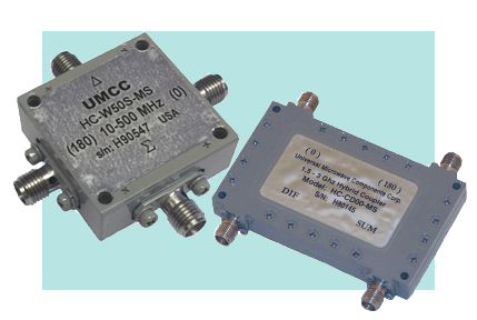
| 180deg Hybrid Couplers | |
|
|
|
| Specifications
are subject to change without notice - Click on the product model number for Specifications-Sheet in PDF - Click on " |
|
|
Sales/Technical Contact Email: Sales@UMCC111.com |
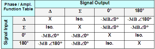
The 180 hybrid couplers are four port devices with non-reciprocal property. Signal incident to the sum port (∑ port) splits equally in phase and amplitude between output ports (0 / 180 ports) and the difference port (Δ port) would be the isolated port. With signal incident to the difference port (Δ port), it again splits at output ports equal in amplitude with one output lagging the other by 180 in phase. Applications of 180 hybrids include phased array networks, mixers, vector modulators, phase detection/shifting devices, and many more. |
|
|
 |
|
Low Frequency Wide-Band 180deg Hybrids
( Lumped Element ) 30 KHz - 2500 MHz |
||||||||
| Model Number |
Freq. Range |
Insertion
Loss Max |
Isolation Min |
Amplitude Balance Max |
Phase Error (-/+deg) Max, (1) |
VSWR Max |
Power Handling CW / Peak |
Outline Drawing |
| 30 KHz - 10 MHz | ||||||||
|
HC-W030-MS with SMA(f) HC-W030-MB with BNC(f) HC-W030-MN with N(f) |
30KHz - 10MHz |
0.5 dB |
25 dB |
-/+0.3 dB | -/+5deg | 1.30:1 | 8 W |
Fig.4 Universal Pkg. |
| 1 - 200 MHz | ||||||||
|
HC-W20S-MS Slimline Pkg. with SMA(f) |
1 - 200
MHz |
0.8 dB | 28 dB | -/+0.3 dB | -/+2deg | 1.30:1 | 4 W |
Fig.5 Slimline Pkg. with SMA(f) |
HC-W200-MS |
1 - 200
MHz |
0.8 dB | 28 dB | -/+0.3 dB | -/+2deg | 1.30:1 | 4 W |
Fig.4 Universal Pkg. |
| 10 - 500 MHz | ||||||||
|
HC-W50S-MS Slimline Pkg. with SMA(f) |
10 - 500
MHz |
1.0 dB | 22dB (0/180) 27dB (Sum-Diff) |
-/+0.2 dB | -/+4deg | 1.45:1 | 1 W |
Fig.5 Slimline Pkg. with SMA(f) |
HC-W500-MS |
10 - 500
MHz |
1.0 dB | 22dB (0/180) 27dB (Sum-Diff) |
-/+0.2 dB | -/+4deg | 1.45:1 | 1 W |
Fig.4 Universal Pkg. |
| 50 - 2500 MHz | ||||||||
|
HC-2500-MS with SMA(f) HC-2500-MN with N(f) |
50
- 2500 MHz |
4.3 dB |
22dB (0/180) 22dB (Sum-Diff) |
-/+2.0 dB | -/+10deg | 2:1 (SUM/0/180) 2.1:1 (Diff) |
4 W | Fig.6 |
1) Phase error is measured in reference to the Median Line |
||||||||
m
|
Narrow-Band 180deg Hybrids ( Stripline
Construction ) 0.5 - 6 GHz |
|||||||||
| Model Number |
Freq. Range (GHz) |
Coupling (dB) Max (1) |
Freq.
Flatness (dB) Max |
Isolation (dB) Min |
Phase Error (-/+deg) Max (2) |
VSWR Max |
Power (Max Input) |
Outline Drawing |
|
| CW/Avg | Peak | ||||||||
|
HC-B000-MS |
0.5 - 1 | 3.2-/+0.5 | -/+0.50 | 26 | -/+5deg | 1.20:1 | 50 W | 3 KW | Fig.2 |
|
HC-B101-MS |
0.6 - 1.2 | 3.3-/+0.5 | -/+0.50 | 24 | -/+5deg | 1.30:1 | 50 W | 3 KW | Fig.1 |
|
HC-BC00-MS |
0.8 - 1.6 | 3.3-/+0.5 | -/+0.50 | 22 | -/+7deg | 1.30:1 | 50 W | 3 KW | Fig.2 |
|
HC-C000-MS |
1 - 2 | 3.4-/+0.6 | -/+0.50 | 22 | -/+7deg | 1.30:1 | 50 W | 3 KW | Fig.2 |
|
HC-C000-MN All N(f) |
1 - 2 | 3.4-/+0.6 | -/+0.50 | 22 | -/+7deg | 1.30:1 | 50 W | 3 KW | Fig.3 |
|
HC-CD00-MS |
1.5 - 3 | 3.4-/+0.6 | -/+0.50 | 22 | -/+5deg | 1.30:1 | 50 W | 3 KW | Fig.2 |
|
HC-D000-MS |
2 - 4 | 3.5-/+0.7 | -/+0.60 | 22 | -/+6deg | 1.35:1 | 50 W | 3 KW | Fig.1 |
|
HC-H000-MS |
3 - 6 | 3.5-/+0.7 | -/+0.60 | 16 | -/+8deg | 1.45:1 | 50 W | 3 KW | Fig.2 |
|
1) Coupling is nominal and includes insertion loss and frequency flatness 2) Phase error is measured in reference to the Median Line |
|||||||||
| All Models: | |
| 50 Ω Nominal | |
| SMA (female) | |
Environmental Ratings: |
||
| - Operating | -40 degC to +85 degC | |
| - Storage | -50 degC to +100 degC | |
| Mil-STD-202F, Method 103B Condition B | ||
| Mil-STD-202F, Method 213B Condition B | ||
| Mil-STD-202F, Method 204D Condition B | ||
| Mil-STD-202F, Method 105C Condition B | ||
| Mil-STD-202F, Method 107D Condition B | ||
Available Options: 1) units with combination of the following options may require some specification tradeoffs from the standard 2) Some options may not be available on all models |
|||
| B1) SMA(M) for Input | - Custom Connector Options | ||
| B2) SMA(M) for Outputs ( 0 & 180 ) | - Etc. | ||
| B3) SMA(M) for All Ports | |||
|
|
|
|
|